Showing posts with label boat maintenance. Show all posts

Monday, July 6, 2015

The Imperial March or ....the Game of Thrones

Keep the Star Wars Imperial March playing in your head...

It was at the end of a fibrous-food filled day, a groan escapes from the bowels of the boat. From below comes the shaky voice of our comrade, "Ummm....I think there's something wrong with the toilet." The dark force has awaken and it has stolen away my happiness. For, I know the implications.
Howdy Ho!

I obviously have a blockage somewhere in the system. Two things have conspired against me:
  1. Over zealous use of toilet paper - It is easy to forget that marine toilets don't like a lot of (any??) toilet paper. In the heat of the moment, the user just wants to get things done...using as many sheets as they feel required. The intricacies of toilet mechanics rarely come into people's minds. 
  2. Ultra plush toilet paper - Anyone who has repaired a marine head knows that it is imperative that only the worst toilet paper should be used in one of these things. The engineers apparently do not have access to 2-ply paper when they develop their models and plans for marine heads. The rule of thumb is that you should only use TP that is guaranteed to tear on first contact. We made the ultimate sin by attempting to use "ultra" TP. 
So, I tear reluctantly into the system. My preliminary research has shown me that the choker valve is a likely candidate. I start by disassembling the main cylinder...hunting for the valve. Eventually I work my way backwards through the system until I figure out that the problem is actually further up the line in the discharge hose. 

Luckily I was at our club pump-out station, so I used the pump-out to slurp out the clog from the discharge hose. Phew! Problem solved...right? Well, not so fast. 

When I removed the main cylinder I noticed that the gasket was missing or had rotted away. Now I had a new problem...a leaky toilet. This is at least as bad as a non-functional head since the leak on the cylinder is ...vigorous. Maybe I should just replace this damn thing with a new toilet, I think to myself. Research time...

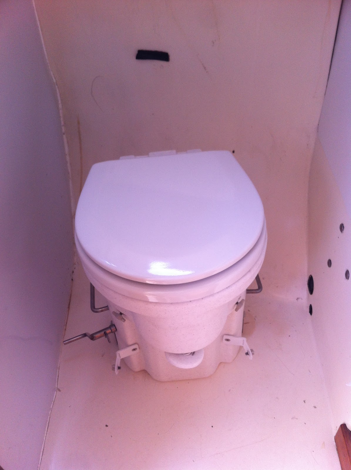
Apparently my boat has been blessed with a Wilcox-Crittenden Imperial 51 head. According to the inter-webs, this throne is a "pearl beyond price, the pinnacle of the nautical plumber's art". I had no idea. 

From what I have read, I would be (at a minimum) ridiculed if I even think of getting rid of this head and replacing it with a $200 plastic atrocity. So, here I am, I need to fix it. 

Thanks again to the inter-webs, I have found a copy of the manual. The best thing about this manual is that the scanned copy actually has proof of its use stained on the cover. This brings a certain authenticity to the document. I feel the pain of the poor soul who put this poop laden paper into his scanner. 

From the manual I find out that there is a service kit available for the head and that a mere $169.95 will solve all of my woes. As per the recommendation of some helpful person on a forum somewhere, I removed the head and took it home for a revamp. A quick two day turnaround from Binnacle got me my parts. 

WILCOX CRITTENDEN 1599 JUNIOR or IMPERIAL MAINTENANCE KIT281971CAD$169.95

I started by disassembling the head and removing as many of the serviceable pieces as possible. If I'm going to do this, I'm going to replace as many parts as I can. 

As I was disassembling it I did my best to keep it straight which direction parts were oriented. The manual isn't really clear in this respect.

Putting the toilet back together was relatively straight forward. No major surprises.

The toilet now works [mostly] normally. I am fighting with an overly strong "Waste Valve Flap Spring" that is doing its job a little too well. More on that later....


Monday, June 1, 2015

Pram overhaul - Part 2

Front seat top installed and bow reinforced 


To see the first post for this rebuild, see here.

I installed a new seat top because the old one was kind of beat up. It was just easier to cut out a new one rather than fix the old one.

Almost ready for paint
I screwed it in and glued it to the seat from and around the edges with thickened epoxy. I then glassed, with epoxy, the whole way around the seat. My goal was that the seat would become a structural component and take some of the pull from the front ring.

I also added extra reinforcement to the top rail of the bow and I glassed this in to the front and side panels to, again, make it stronger and tie everything together.
Finished side with no stringer

Finished bow and lift straps
Since my new boat has davits on the back I also wanted to add lifting points on the dinghy. I bought some 1" galvanized rings at the local hardware store. I put hardwood mounting plates on the inside of the hull and used 1/8" aluminum plates on the outside for backing. I thru bolted these.

I placed the lifting points as close to the seat frames as possible so that they would take some of the squeeze that I expect will happen in the lifting.

I haven't quite perfected the lifting straps to work on the davits but I'll add an article later once I've gotten those figured out. The lifting straps did make it convenient for painting since I could do both top and bottom in the same session!

I finished her up with four coats of Rustoleum and she seems to be working out well.


Diesel tank cleanout

Replacement filter

Prelude

It started innocently enough. Actually, to be accurate, it didn't start.

It was a peculiar thing. Shackleton performed brilliantly on my delivery cruise up the river two weeks ago. Eight hours of cruising with several stops and starts and it worked flawlessly.

Two days later, I crank her up and she runs for 20 seconds and dies. Odd.

My first diagnosis was that there was probably something (either water or dirt) clogging the fuel filter. It had been a particularly rough day on Grand Lake when we came in to the harbour and I figured that it had probably just soiled the filter when the sediment in the tank sloshed around.

I drained and cleaned the primary filter. No luck.

I replaced the secondary filter...no luck.

I bled the system. I bled the system. I bled the system. No luck.

Since I am new to the wonderful world of diesels (previous engine was an Atomic 4) I figured that I was doing something wrong in the bleeding process (even though the manual on the Vetus M4.15 says that it is "self bleeding".

After many hours of unsuccessful bleeding attempts I decided to actually think through the problem...

Lesson #1 - Stop and think. (sure, it seems obvious now!)

A bit of experimentation finally lead me to figure out that I wasn't getting any fuel from the tank. (another sailor had actually mentioned this as a possibility early on...and I had quickly forgotten about it).

Lesson #2 - Really pay attention to what the experienced sailors say!

I removed the access hatch for the tank and quickly realized the root of the problem.

Goo filled bucket
Lesson #3 - Make sure that whatever you use for a gasket on your fuel tank is actually compatible with diesel fuel. The previous owner had not. He had used some sort of a rubbery material that had since partially dissolved. This partially dissolved goo was now all through my tank. Little black jelly bean sized goo pieces had lodged themselves into my intake hose.

The fix


  1.  I removed all 40 gallons of fuel into jerrycans. The last 2 cm at the bottom (where the sludge was mostly), and the sludge, was removed into a separate container for disposal. I used a borrowed diesel lift pump hooked to my battery to pump out the fuel. This was a slow process. I used cheesecloth over the end of the suction tube to keep it from getting clogged. 
  2. I cleaned the tank. I scrubbed it with rags and used a porous sponge to sock up the grime and sludge. I rinsed the tank with more diesel using the lift pump in reverse. 
  3. I disconnected and blew out the intake hose. Not to self...bring an air pig for this. Diesel tastes terrible!
  4. Tested the engine...and it worked!
  5. I made a gasket out of 2mm cork.
  6. Using a Sue Grafton novel of my wife's (haven't told her this yet) as a drilling backer I pre-drilled the gasket holes.
  7. Re-installed access plate
  8. Sue Grafton brand drilling backer
     
  9. Cleaned up all of that diesel that I had carefully tried not to spill.

Hopefully my cork gasket will last for a few years without turning into another mess. The inter-webs assure me that it will be ok.

The positive outcome from this ordeal is that I now have a much better understanding of my fuel system. 


Completed access plate with gasket
Asian strainer with cheese cloth for removing chunks

Monday, April 20, 2015

The Cat came back


Platinum Cat Heater - Model 6P12

The built in heater on our new-to-us boat, Shackleton II, was one of those nice-to-have features that we were excited about. So we were disappointed when we couldn't get it to work.

Since this was one of many systems on the boat that I was unfamiliar with, I initially thought that it was operator error. But, after some digging, and posting to SailNet forums, I was confident that I was doing it right. It apparently really is as easy as turning on the power and turning up the thermostat. But it still didn't work.

I dug around and figured out that the heater is from a company called A&L Enterprises. I reached out to their generic email address and received a quick response from Arnie. He explained that the model I have is an antique from the early 80's. I wasn't optimistic. Surely if it was that old it would be unserviceable.

Arnie proceeded to send me several manuals, service updates, and detailed troubleshooting instructions. After a bunch of back and forth I solved the problem. The fan blower was rubbing on the housing and causing it to fail. Happily I now have a great working heater!

The service from A&L Enterprises was exceptional. They could have easily told me that it has to be replaced, since it was so old, but they didn't. When I do need to replace the unit, I know where I'll be shopping.

Monday, June 9, 2014

New prop

Indigo Propeller
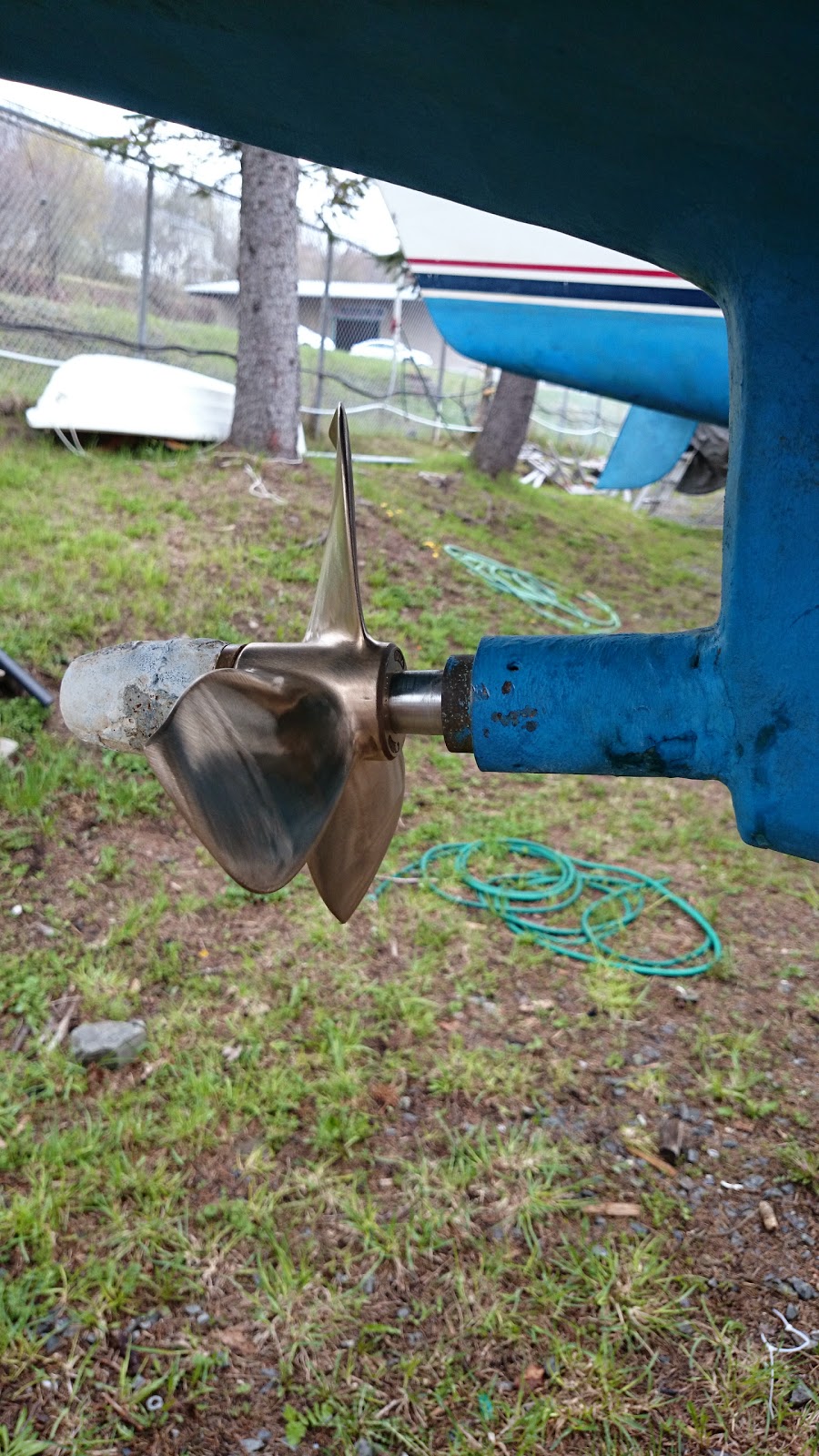
According to the specifications, the Atomic 4 should have a cruising RPM of 1900 and a wide open RPM of 2400. Apparently most people have too large a propeller and too low of an RPM. My problem was the opposite.

My cruising RPM was 3200 at 5 knots and if I wanted to get to 5.5kn I would be pushing 3500 RPM. While this RPM is still within the tolerances for the engine, it created a lot of unnecessary noise and vibration.

My old prop was a two blade 12x6 and it was undersized. I'm sure this helped a bit in my club racing since it had lower drag, and it was tolerable for cruising under power but it was an issue fighting heavy currents large waves. A sketchy trip through Letete Passage last year (yes, at the wrong tide...) confirmed my need for more available speed.

Indigo PropellerAfter a recommendation from Bill on Lady Hamilton I picked up a prop from Indigo Electronics. Indigo was very easy to deal with and were quick sending out the prop. The prop is a three blade 10x7.4 and seems to be of high quality.

After finally launching this weekend I was happy to test out the prop and see the results. My cruising RPM is now at 2600, at 5kn. This is still a little higher than desired, but much better.


Tuesday, May 20, 2014

Building a new tiller

The tiller on Salammbo was looking pretty decrepit and it was time for either a refinish or a rebuild. Since the tiller had already been fixed at least once in the past, and wasn't looking great, I decided to go new. I also had some nice 1 1/4" thick white ash available from a paddle making project my Scout group did a few years back that I knew would look great as a tiller handle. White ash is strong and durable. 

  • The first step was to simply trace my old rudder onto the stock. I liked the existing rudder feel so have no need to change the shape. 

Tracing the tiller
Tracing the tiller

  • Cut out the rough shape with a jig saw. 

Rough cut tiller
Rough cut tiller
Rough cut tiller

  • I used an aggressive rasp to remove the bulk of the material. A less aggressive file tuned up the shape.
Rasp shaped tiller
Rasp shaped tiller

  • I used a power sander with 60 grit paper to smooth out the rasp marks and followed that up with 120 grit and then 220 grit.


Finished tiller
Finished tiller


Tuesday, March 11, 2014

Atomic 4 Rebuild - Transmission cover and housing - Part 1

Atomic 4 Transmission - Pre-dissasembly
Transmission - Pre-dissasembly

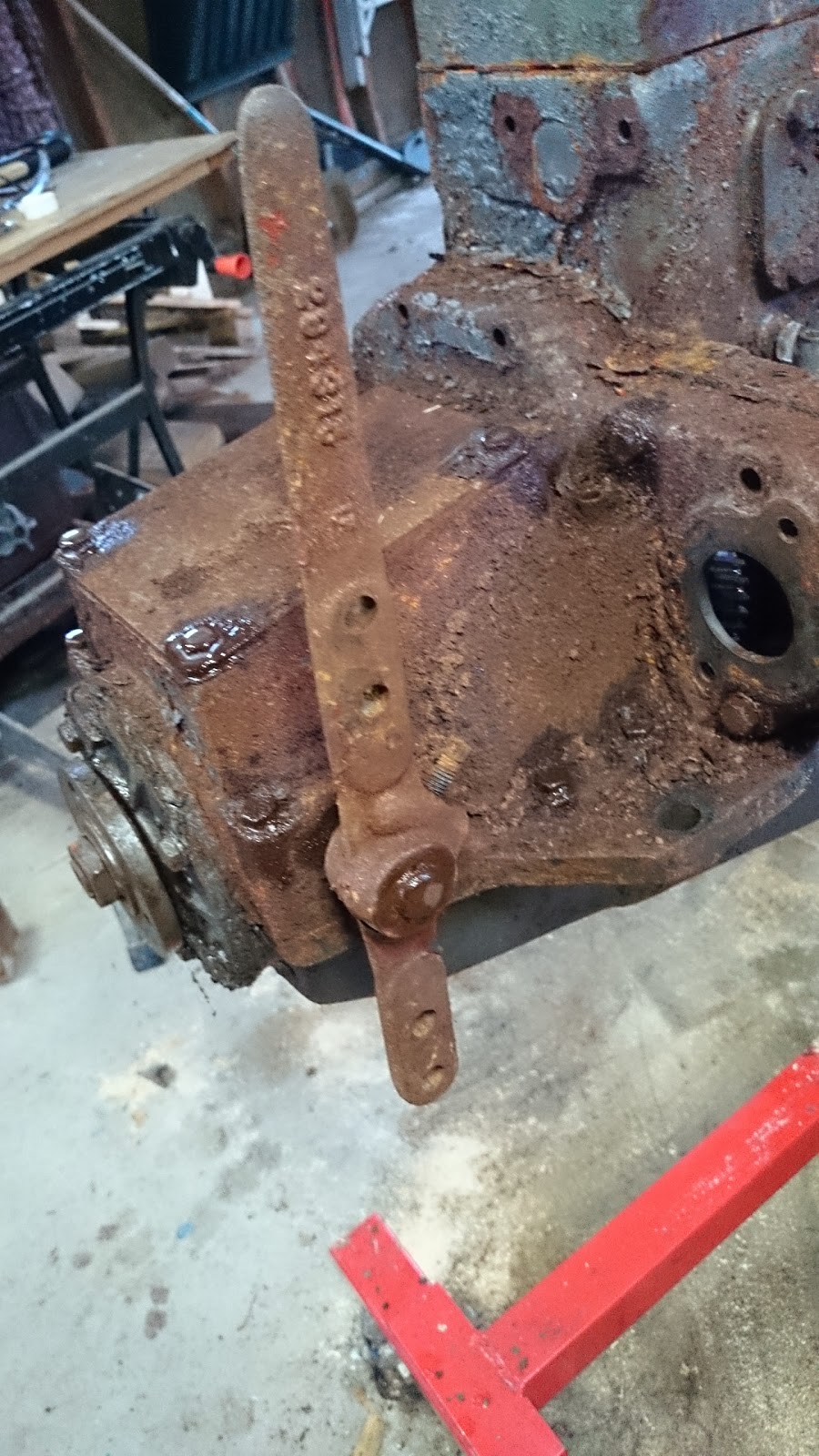
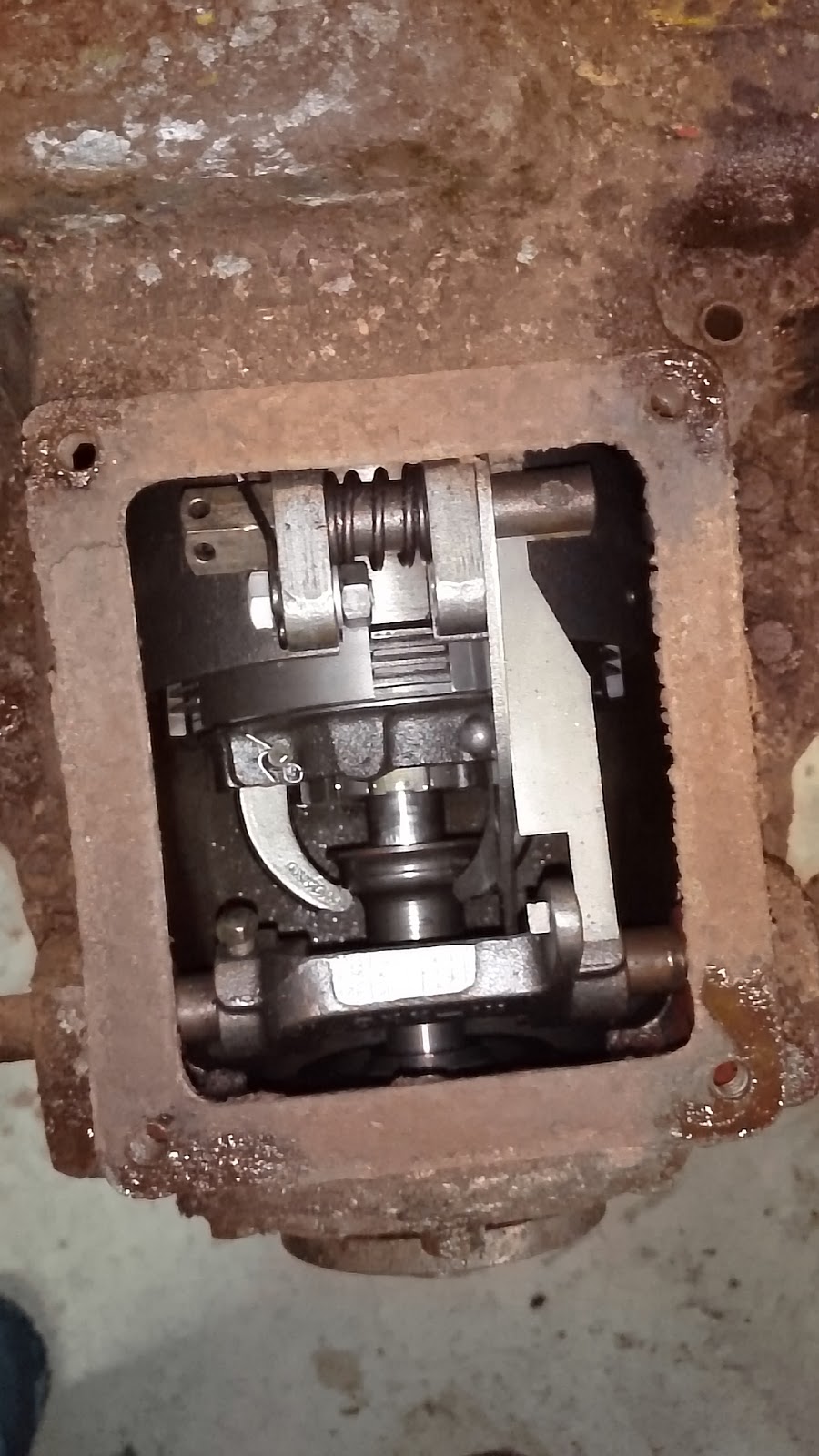
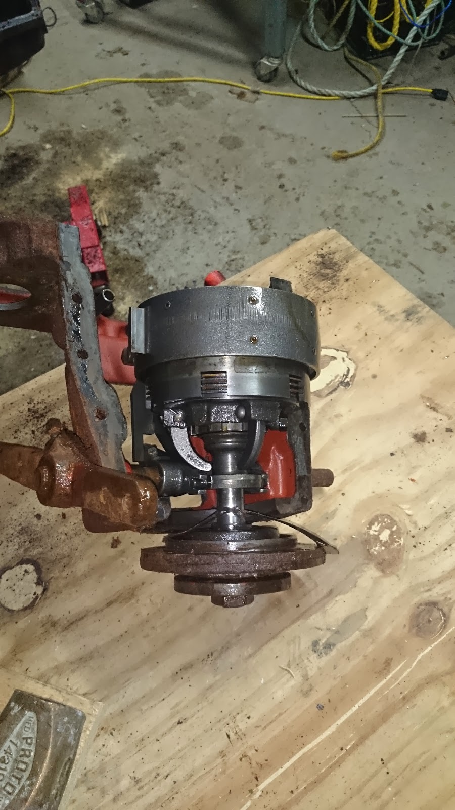
Removing the transmission cover and housing was a bit of a challenge...and continues to be.  I also don't think that I did it correctly. Hopefully I didn't cause myself grief down the road when I try to put things back together.

I removed the four 3/4" bolts (1/2") holding the transmission cover, exposing the transmission.

Atomic 4 transmission with Cover plate removed
Cover plate removed
I the removed the thrust bearing (the round plate at the back of the transmission). This is held on my six 1" long bolts (1/2").

Rear of transmission before removal

I have since discovered that I should have first removed the tail shaft nut first.

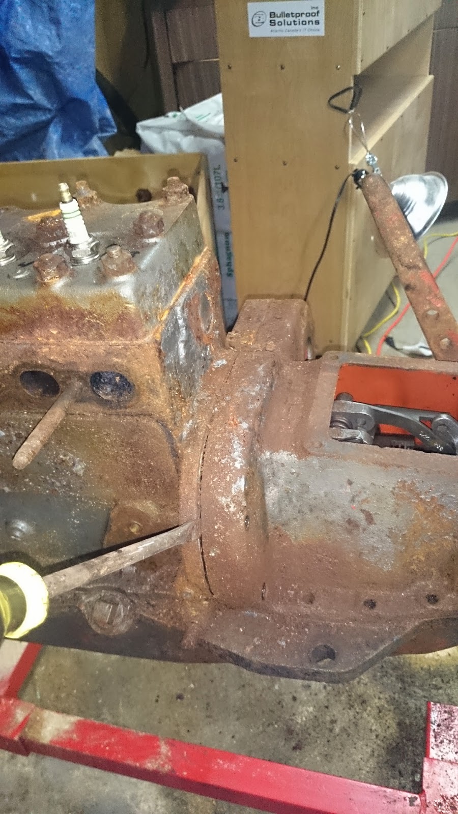
Removing the transmission housing was difficult, as it was securely stuck by gasket goop and decades of rust.

I first removed the ten bolts holding it in place. These include four 1 7/8" (1/2"), two 2 5/8" (1/2"), and six 3/4" (1/2").

I was apprehensive about beating too hard on any particular piece because I wasn't sure how solid they were. In the end I used a knife, large screw driver and hammer to poke, pry and beat the housing until it dislodged. No damage done. (except the gasket)

Atomic 4 transmission housing prying offAtomic 4 transmission housing prying off


Removing that nut is now much more difficult (I haven't actually figured out how to do that yet) since the nut spins on the bearing (surprise surprise).

I thought it would be easier to find something to pry on once I removed the whole housing and transmission. Not so much...

Atomic 4 transmission housing and transmission removed
Housing and transmission removed together
Here is the finished product.
Atomic 4 without transmission

[All of the posts associated with this rebuild are available under the search label Atomic 4 Rebuild.]


Sunday, February 16, 2014

Atomic 4 rebuild - removing flywheel housing


Atomic 4 flywheel cover
The flywheel cover is held on by nine 1" (9/16") bolts around the perimeter on the back side of the cover, each has a lock washer. There are also 2 similar bolts on the top front of the cover.

All except the bottom two are easy to get at and remove. Those I couldn't get at with a socket but was able to eventually free with a short wrench. Removing two of the boards from the bottom of the wooden stand made the job somewhat easier.

The cover is also held in place with several alignment studs. A rubber or wooden mallet can be used to tap the cover off once the bolts are removed.

Have a container ready when you take the cover off because you will lose some oil.

[All of the posts associated with this rebuild are available under the search label Atomic 4 Rebuild.]

Atomic 4 flywheel cover removed

Sunday, January 12, 2014

Atomic 4 rebuild - removing the waterpump and thermostat

The next step in the disassemble process was to remove all of the cooling related pieces. All of the cooling lines are going to need to be replaced as they are disintegrated.

Water pump to thermostat hose 

  • Remove rubber cooling hoses.  There are 4 hoses that are involved in the cooling system:
    •  Thermostat to manifold - 1/2" hose - 4 3/4" long
    • Mid-block to thermostat - 1/2" hose - 7" long
    • Water pump to mid-block - 1/2" hose - 10 1/4" long
    • Manifold loop - 1/4" hose - 18" long

  • Remove thermostat - The thermostat is held in place by two 9/16" nuts. There was no gasket on the thermostat. I tested and cleaned the thermostat. 

[All of the posts associated with this rebuild are available under the search label Atomic 4 Rebuild.]

Atomic 4 rebuild - Removing water pump and accessory drive


The water pump is attached directly to the accessory drive bracket with two 9/16" (1" long) bolts.

I removed the impeller for inspection (and because I haven't had a good look at the impeller housing before since my current engine's is crammed in the worst ungodly position in my engine compartment).

The impeller was in good condition but I will replace it since it is old. The impeller is held on with 4 flat head machine screws (1/2" long). There is a full description of each part in the impeller system on the Moyer impeller parts page. The o-ring gasket on the impeller plate is missing, or so disintegrated as to not be recognizable. I will replace that on reassembly.

There is a gasket on the drive side of the assembly. It will need to be replaced.

The accessory drive is held on by two 9/16" bolts (2 7/8" long). One of these bolt heads is stripped and will need to be replaced. I couldn't remove the other bolt fully yet because the engine mount is in the way.

The Moyer site has a great page on the accessory drive. http://www.moyermarine.com/access_repair.htm


[All of the posts associated with this rebuild are available under the search label Atomic 4 Rebuild.]


Friday, December 6, 2013

Atomic 4 Rebuild - Introduction

Atomic 4 - right side with serial number

Recently I came into possession of an Atomic 4 engine. A local sailor upgraded to a new boat and had a spare engine from his old boat that he had intended on rebuilding. I am taking over the rebuild project.

Goals

I have a few goals for this project:

    Atomic 4 - frontAtomic 4 - left side
  1. Increase knowledge: Increase my knowledge of Atomic 4 engines so that I am more capable of troubleshooting and repairing my boat when needed. I am not mechanically inclined but need to be more self sufficient given my desire to cruise further in this boat.
  2. Spare: Given that my current A4 is 42 years old, a spare is important to avoid lengthy losses in precious summer boat time.
  3. Upgrade: Assuming that I am successful in this build, my plan is to eventually swap this new engine with my old one to provide more reliability and performance.  Not that my engine has been particularly problematic, it has been reliable for the most part.

Mechanical ineptitude 


Ineptitude may be a little strongly stated, however, I have very little mechanical experience. Over the last few years I have tried to increase my knowledge of engines and marine systems and I have successfully done some maintenance and repair jobs on my A4 (thermostat and exhaust manifold were the big ones).

All of this is to say that this engine rebuild will be completely new ground for me. While this is a great experience for me, it does mean that you should take my techniques, suggestions and recommendations with a BIG grain of salt. Talk to a mechanic if you want real advice!
Atomic 4 - back


My primary resources, initially, for this project will be:
THE COMPLETE OWNERS & SERVICE MANUAL FOR THE 
UNIVERSAL ATOMIC 4 GAS ENGINE

Engine Builder's Handbook

I will chronicle this rebuild as detailed as possible so that others might find something useful out of it. All of the posts will be available under the label Atomic 4 Rebuild.


Saturday, November 2, 2013

Atomic 4 Thermostat cleaning

While investigating cooling issues in my Atomic 4 I came across an FAQ at the Moyer Marine site that described cleaning the thermostat every season. "It really is better to use a thermostat in the Atomic 4, and to keep it clean by soaking it in vinegar every season." 

While I have had my thermostat out annually for winterizing, I have never cleaned it. So I decided to give it a try.
Atomic 4 Thermostat
Half way clean, after 2 days soaking in vinegar
I had no idea how dirty the thermostat was! In fact, I though that the thermostat had been rusty but, now that it is clean, I realize that the rust was just gunk. 40 years of gunk took 3 days of soaking to clean (and 3 changes of vinegar).

I also wasn't sure what temperature rating my thermostat was rated for so I tested it by boiling it.

Boil testing Atomic 4 thermostatBoil testing Atomic 4 thermostat

The thermostat started opening around 125 degrees Fahrenheit and was fully open around 160 degrees.It was approximately 1/4" open at it's fullest. I'm not sure if either of these are measurements are within spec because I can't find a good reference online. If anyone knows, please comment below.

I'm not sure if my dirty thermostat was the cause of my cooling issues but it couldn't be helping.

Friday, May 11, 2012

Composting Toilet Installation

Installation of the composting toilet itself is pretty straight forward. Much more effort was required removing the old toilet and adjusting the floor than was required for the actual installation of the toilet.

    Remove the existing toilet system parts, including:

    • Holding tank
    • Holding tank pump piping
    • Y-valve
    • Toilet and piping. Removing the toilet itself proved most difficult since the bolts holding it in place were stripped. A hacksaw was the final solution.

    Test fit
    Test fit the Airhead toilet. The back few inches of my head has a significant sloped area. This greatly reduces the working area of the toilet. After test fitting I decided to add a raised floor so that I could get the maximum front-to-back clearance.


     Make raised floor.
    I made the raised floor out of 1/2" plywood, cut to shape using a cardboard template and supported by 1x3 spruce boards. I stained and varnished the floor to match the rest of my bright-work. I used brass L-brackets to hold the raised floor in place. This will allow for easy removal if I need to get access below.

    Install Airhead unit. The toilet unit itself is literally as easy as screwing in 4 screws into the two brackets.
    Installed with raised floor

    Install air fan. I have an existing cowl vent into the bathroom. I simply screwed the fan assembly on top of the existing vent whole.
    Fan assembly attached to cowl vent

    Run vent hose. I used 6 feet of vent hose and simply attached it to the wall with 1 1/2" plastic pipe brackets. Once the pipe is tucked in properly it isn't as ugly as I expected.

    Run wiring.  I used standard 14 gauge wire (overkill I think) to wire directly from the fan to my auxiliary battery. I have two medium sized solar panels that keep up the charge on the battery. I don't even notice the load of the vent fan on my electrical. 

    Test run! I will update later with my production review of the toilet.

    Wednesday, May 2, 2012

    PVC Pipe Winter Boat Cover Frame


    After several years of mediocre success covering my boat with a traditional wooden boat cover frame, last fall I decided to change it out for a frame made from PVC pipe. Now that it is spring and the frame and cover have survived the winter flawlessly I figure I should share my design.

    I decided to use 1 1/2" PVC pipe since it is only a little more expensive but much sturdier than 1 1/4" pipe. I also made the arbitrary decision to space my supports at 3'.


    1. Determine the number of supports by dividing your boat length by 3. 
    2. Take a width measurement at each support location.
    3. Use a Triangle Solver or some basic trig to determine the lengths of pipe required for each side given width and the angles (90 and 45 degrees).
    4. Cut the pipe to length
    5. You will also need to cut 3' lengths of pipe to go between each support and a length of pipe for each end.
    6. Make the top 90 degree connector
      1. I used a single 90d PVC female-female connector attached to a female-female straight connector with a machine screw.
      2. Drill a hole in the center of the 90 and straight connectors.
      3. Attach them together using a screw and nut.
      4. I also drilled holes close to the edge of each side of the straight connector to fasten the connector to the lateral support pieces.
    7. Glue the entire support structure and connectors together using PVC pipe glue.
    8. Assemble the whole thing together with pipe glue using the vertical supports and the 3' PVC pipe sections. Do NOT GLUE!
    9. Use additional screws to hold the 3' pipe sections into the connectors.
    10. Cover the connectors with foam to prevent tarp chaffing. 
    11. Use tie-wraps to secure the frame to lifelines or whatever else you have that is sturdy.

    This whole project took approximately 2 hours once I had the design figured out. Assembly took approximately 30 minutes. That is a far cry from the hours that my previous wooden structure took to assemble.

    The slope of the frame seemed sufficient to keep snow from piling up on top. I didn't have to shovel it at all through the winter.

    Wednesday, April 4, 2012

    Prop Nut Zinc Anode

    My Hughes 29 has spent the vast majority of it's 40 year life in fresh water. Apparently electrolysis is still possible in fresh water but it certainly isn't fast acting. My boat hasn't had an anode installed (in recent history anyways) and shows no sign of corrosion. However, I do plan to hit salt water so I have been on the hunt for an appropriate anode.

    The problem with the Hughes 29 boats (confirmed by other owners that it's not just mine) is that there is very little clearance between the prop and the shaft housing. On my boat there is only 3/4" clearance.  That isn't enough room for a standard shaft mount anode. 

    After much searching, I found a source for an anode that would work. It is a  prop-nut mounted anode.  The following are the part number and spec for the anode. 


    CMPNCC10 - For 1" diameter propeller shaft. Complete set, zinc and bronze nut.

    Shaft Size: 1" (25mm)
    Length: 3" (76mm)
    O.D: 1 7/8" (48mm)
    Weight:  1.38 (0.63kg)
    Thread Size: ¾"NC10
    O.D.: 1 7/8" (48mm)
    Fastner: 5/16-18x1 socket head w/patch

    These anodes are available online at The Binnacle.